Butternut HF9V Installation
Assembly and initial installation of the Butternut HF9V multi-band ham radio antenna.
Deciding on an Antenna
I live on a fairly small lot in Edmonton, AB, CA (grid square DO33gn, for those that are curious). The problem with this sort of lot is there is no space for a large HF antenna. This leaves the options of what to put out in the yard for long distance communications something that is vertical.
Dipoles are nice and simple to build, they have good coverage and other useful aspects, but they are also (in general) huge. Since anything that is parallel to the ground is limited by the boundaries of my lot, a larger dipole than one built for 20 metres is not really practical. When using a vertical antenna, it just has to go straight up and not use a lot of ground space. This allows for a much larger or complicated antenna than would otherwise fit.
I spent a few months looking around at various antennas and designs and made my final decision to pick up the Bencher Butternut HF9V. Though expensive, it had good reviews, would fit nicely into my yard and still be shorter than my house, and I have to admit it looks quite amusing and impressive to me. (My neighbour returned home while I was erecting the base of the antenna and she was really caught off guard by the appearance.)
I ordered the antenna originally from Bencher themselves, but they were backordered. I went ahead and ordered it from HRO instead as they had them in stock.
A Package Arrives
Tuesday afternoon a package arrived from Ham Radio Outlet. It was the Butternut HF9V I had ordered two weeks earlier. For the low, low cost of about $495.00 USD, you too could own one of these antennas. Sure, it is fairly expensive, but I’m pleased with the results after just my first night of testing.
This post is all about the assembly of the antenna and the initial phase of tuning it up. As for the amount of time it took to get from unpacking it to using it on the air, the total time was about 4 hours - including the time spent driving the support rods into the ground. The antenna comes in a very compact box which I found easiest to unpack by simply tearing all the cardboard to pieces.
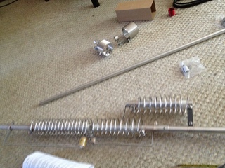
Unpacking
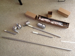
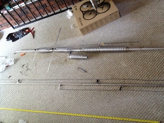
After it was unpacked, the main parts of the antenna like the coils and tubing were easy to see. The rest is in the cardboard rectangle. In that piece, you’ll find all of the nuts, bolts and other gadgetry needed to put the antenna together. You may notice I’m putting this together on my living room floor. Keep in mind that the full length of the antenna is 26 feet, so indoor assembly may not always be an option. It does primarily go together as two long segments, but the one is easily 15 feet long (the upper section) and needs to be put together in one piece to run some wires on.
Starting to Assemble
The manual is reasonably clear on the steps, just not always reasonably clear about identifying the part you want to work with. It has a diagram of all the parts on one sheet with their letter designators that are used throughout the assembly instructions. One common complaint I saw from other users of this antenna was the lack of diagrams in the manual. Overall, it wasn’t all that bad, but a few images (at all) during the instructions phase would be most helpful in ensuring you put the right pieces in the right places.
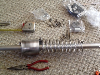
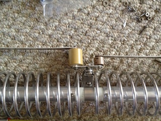
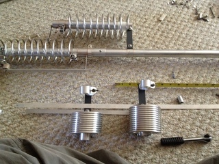
The image is after placing the 80/40m coil onto the main tube. The main tube is actually split into two pieces (known as B and B1 in the manual). They are split by a piece of fiberglass rod which is where the centre clamp of the 80/40m coil assembly attaches. This step was really quite straight forward. Measure, align and use the wing nuts to tighten the coil ends. The extended coil in the image is the 40m coil.
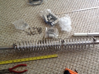
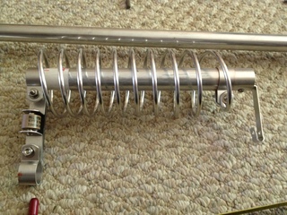
There’s another photo of the 80/40m coil from after stretching out the 80m coil.
Capacitors
This antenna uses two capacitors, a 200pF and a 67pF, to provide matching on 80m and 40m. They were really straight forward to assemble. However, attaching their brackets to the main tube was actually a bit tricky to keep everything in alignment. Being a bit of a perfectionist for things being straight, I spent some extra time here I probably really didn’t need to.
30m Coil
The 30m coil is the strangest attachment to the main tube in the kit. It attaches to the fourth turn of the 40m coil and the main tube via an arm with an embedded capacitor. Attaching it to the coil and the main tube took a little wiggling around to get it over all the bumps and curves. A little bit of the anti-oxidant paste on everything and it was bolted in place. At this point, it’s starting to look quite a bit like the photos and diagrams of the antenna.
17m and 12m Coils and Crossbars
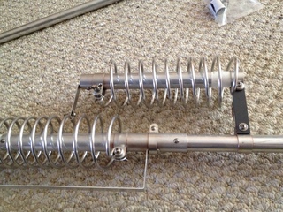
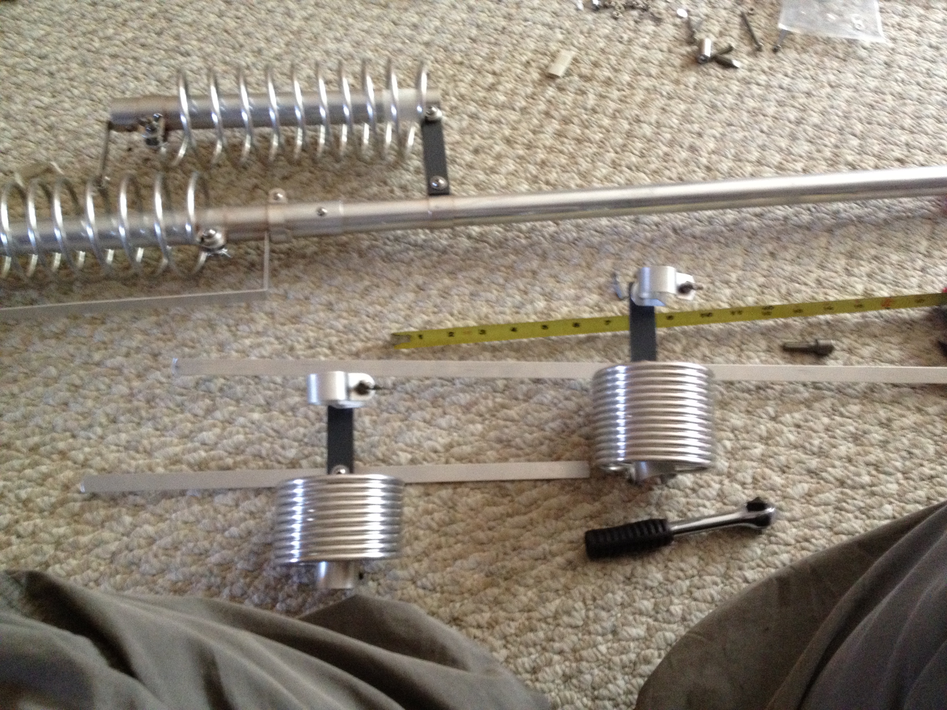
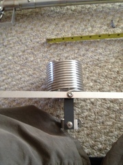
The 17m and 12m coils have metal strips along their tops. They attach with nuts and bolts that are already on the coil assembly out of the package. The two coils are very close in size, but the 17m is larger by a few turns. The 17m strip is substantially larger than the 12m strip.
I took a photo of the two coils side by side to show the difference. The right hand coil is the 17m coil. I found that attaching the two strips, it was hard to get them to stay perpendicular to the coil body and insulation arm. In the end, I just adjusted the angle after the entire antenna was assembled and in the air.
Completion of the Lower Segment
From the beginning, the 80/40m coil went on first, then the 30m attached to the 40m coil and the main tube, then the 17m and 12m coils and their metal strips. At this point, the entire lower assembly is completed and in one piece. I tightened up all the bolts and wingnuts to keep things secured after having checked that it was all looking put together correctly.
Wiring up the 15m and 6m
Attaching the loose wires for the 15m and 6m sections was not very hard at all. It is just a long segment of the antenna to work with. It took up my entire living room in length and a little bit of the dining room. The insulating brackets weren’t critical on their positioning and with the wire being single-ended, the position of the attachment bracket was the only thing to really measure.
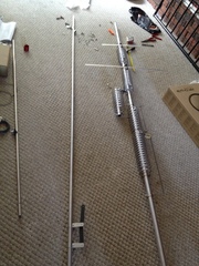
Getting it Raised
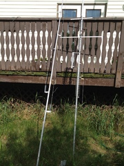
Getting the antenna outside was, thankfully, straight forward by nature of being a straight line from the living room to the back yard. It would have been impossible to get around any corners with the antenna’s upper section. The lower section was small enough to stand up and walk around with.
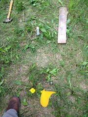
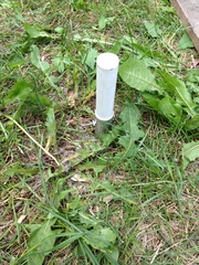
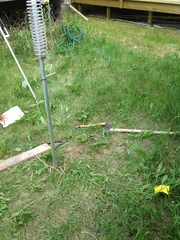
The very first instruction in the assembly manual is to install the mounting post into the ground and attach all the ground radials. I skipped that step since I was just going to assemble the antenna on my floor. At this point, I gave a go at driving the 2 foot post into the ground.
The entire antenna is supported by one bolt on the upper part of the fiberglass insulator. The other bolt is the ground and shield connection for the radials and coax. The lower section of the antenna fits snugly around the fiberglass base and is really easy to put together.
Attaching and Running the Radials
According to Bencher and many others, a vertical antenna is only as useful as the quality of the ground radials attached to it. You can read reports of people using anywhere from 4 to 120 radials.
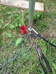
I had decided that the easiest way to get started on my ground radials was to order the Ground Radial Kit from Bencher along with the antenna. It comes with about 360 feet of wire cut into 12 strands and terminated in ring terminals.
At around 30 feet long each, they extended well into my neighbour’s backyard. Conveniently, being a new house on that lot, the fence was torn down during demolition of the previous house. That gave me a fair bit of room to work with in laying out the wires and getting things sorted out.
Completion
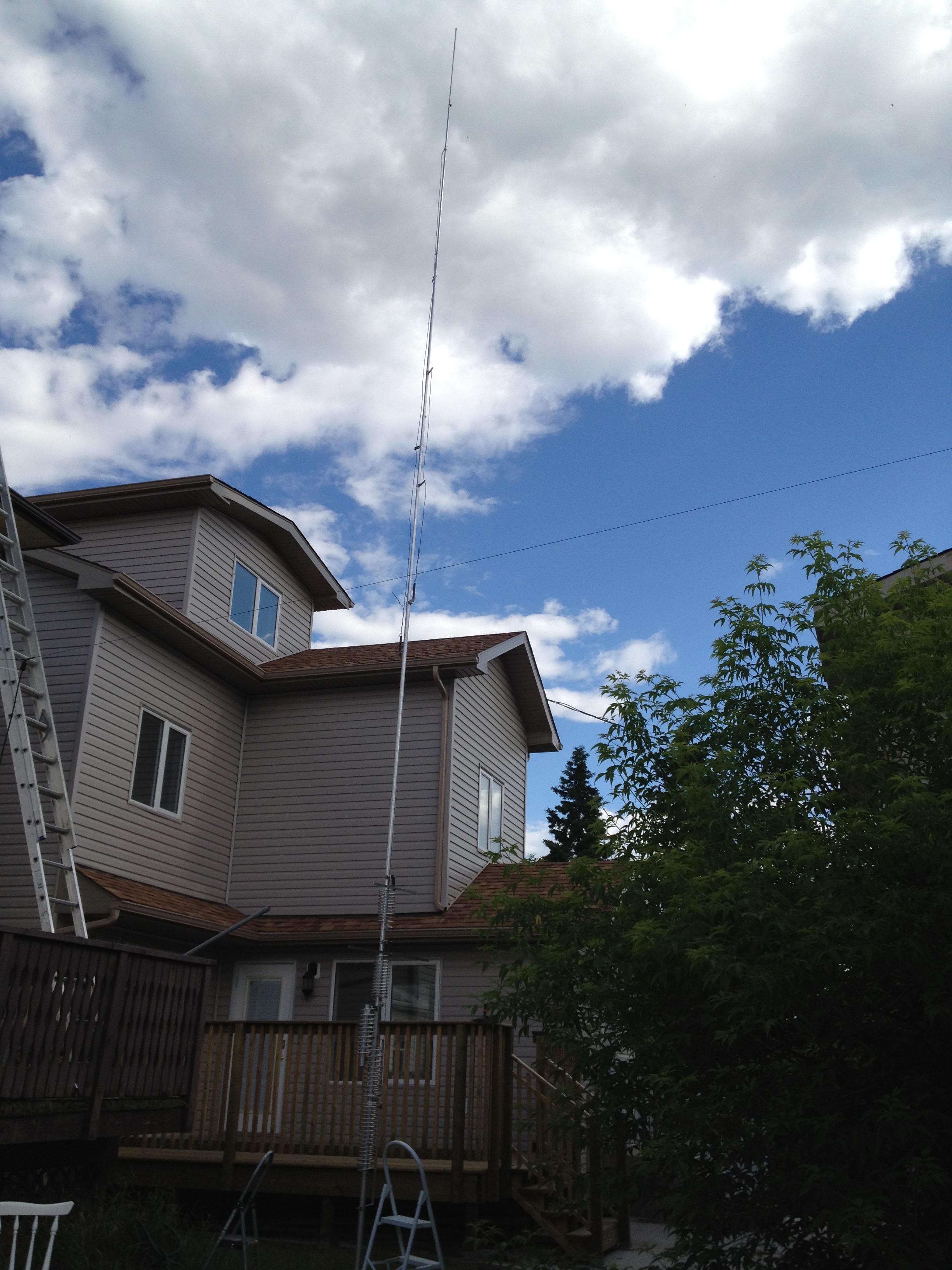
At 26 feet, this antenna is a monster in my backyard and rivals the height of my house. The antenna is positioned as far as reasonably possible from overhead power lines and guyed in such a way that it will have great difficulty falling anywhere near the lines.
Post Installation Storm
After installation, the weather turned superbly ugly with hail, severe thunderstorms and heavy rains. The good news is, the guying and antenna structure was sound, which the storm helped me see clearly by showing how far the antenna would deflect in the wind.
Initial Tuning Results
Due to the large storm, I was only able to really tune up the 80m segment of the antenna before I had to go inside. The 80m segment managed to be tuned to 1.6:1 with around a 50-80kHz bandwidth just by moving the coil around a little.
I later used the antenna with an MFJ tuner on 14.070 MHz to talk to a fellow from New Zealand for an hour or so (using Olivia 6/500) with just 10W of power. The antenna made a stunning difference in the amount of noise I was receiving on my rig compared to my homemade 20m dipole hanging just feet away.
Conclusion
Basically, I’ve only had the antenna for one day, but I have already talked further than ever before and heard more traffic on the air than ever before. That was the goal of the project and I’m happy to report it seems to have worked out. I’ll post again about the tuning results and further performance reviews.
In the meantime, you may wish to see the rest of my hobbies or more about my amateur radio hobby.